Equipment
small updates 7/1/2020
current update, the current station setup is a FT-847 covering lots of bands with additional linear amps for 144 and 432mhz. and independent 70MHz station (allowing multiple band monitoring)
The 'usual' kit for various bands are:
50MHz FT-847 > 3dB collinear / Moxon
70MHz Shimizu SS105s + High dynamic Ukrainian transverter + Pye A200 linear amp > 4el Yagi
144mhz rig FT847 or FT221R+Mutek > KLM160 Amplifier > 9el 144MHz 9 Element Powabeam FLOWA (CQM9UZ2) Yagi + DG8 masthead pre-amp
70cm FT847 + BNOS 60w amplifier + 15 element home brew yagi with masthead pre-amp
23cm currently working on a masthead box for transverter and amplifier to feed a 70 element CQM design yagi.
The aerial setup has not changed much recently, a 2m 9el Powabeam, on 4m I have a 4 element J-beam yagi.
a new 'white stick' SQB1000 6/2/70cm gives me access to 50mhz to play with the Es openings with the FT-847, the Moxon is down at present for refurbishment over the winter.
I will try to keep the station picture up to date with the current aerial selection
I have various ex-commercial radios for FM modes, a Simoco SRM9030 on 70cm, a Philips FM1100 on 2m and another on 4m
Various other rigs for various bands, the old faithful FT101b has seen long service, mainly driving transverters in the past but now on HF.
As a useful offshoot of my business I have available a wide range of communications test equipment with signal generator capabilities up to 2.7GHz, frequency counter up to 2.6GHz and spectrum analyser up to 1.5GHz, along with numerous other test and measurement devices and off-air frequency standards.
Shimizu
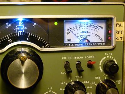
Shimizu Denshi SS105s.
These were on the market in the 1980's and were sold as a part-built kit.
The main units were ready assembled but one pcb was just a bag of parts and a few sheets of instructions for assembly and alignment. It performs remarkably well and was ideal for driving transverters for my main interest in VHF.
It has had a few slight modifications and improvements during its lifetime, the latest is LED dial illumination. It has indicators to show when repeater shift is active for use with a 2m transverter, also when the HF PA is switched on. The RF gain circuit was modified to operate on the front end dual gate mosfet as originally it only affected the agc and failed to control the gain !
ESR Meter for capacitor testing
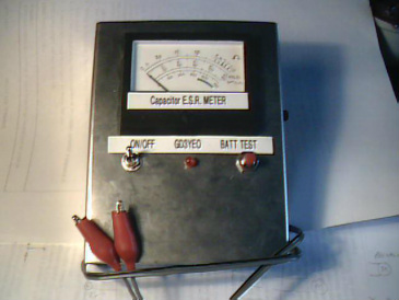
Home built ESR (equivalent series resistance) meter for testing capacitors
bases on this article with slight value changes to suit an available transformer and meter. There is a 'zero set' control on the side, and runs on a pp3 battery.
bases on this article with slight value changes to suit an available transformer and meter. There is a 'zero set' control on the side, and runs on a pp3 battery.
Pye A200 linear conversion to 70MHz
I had a Pye A200 in the 'M1' band variant, which is about 100MHz, which I got to work on 4m.
There are a few websites with mod details but usually for the E-band version, the 70MHz website has download links for the circuit diagram
http://www.70mhz.org/a200_amplifier.pdf
Here are a few notes of what I did to get the M1 to work.
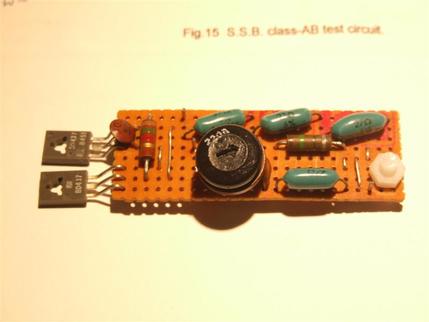
make up a bias module, a small piece of vero with 2 power transistors off the end, mounted on the end of the heatsink case, as per circuit in GM3SEK's site and also on Philips data sheet for BLW60C
I used BD437. one high wattage resistor I made up with 3 smaller in parallel for the size in the space available. I calculated I needed about 10R 10w (I think I had 27R x3 which was the nearest thing I had to fit the space) This bias circuit replaces R18 which is removed, and linked to the bias pcb with the red wire, the bias to the PA is fed via a choke
(I think the lower green resistor is across the pot to get near the right value) the nylon nut and bolt are just a spacer to prevent the board touching the heatsink, it's all just held with the transistor mounting bolts (with insulators under)
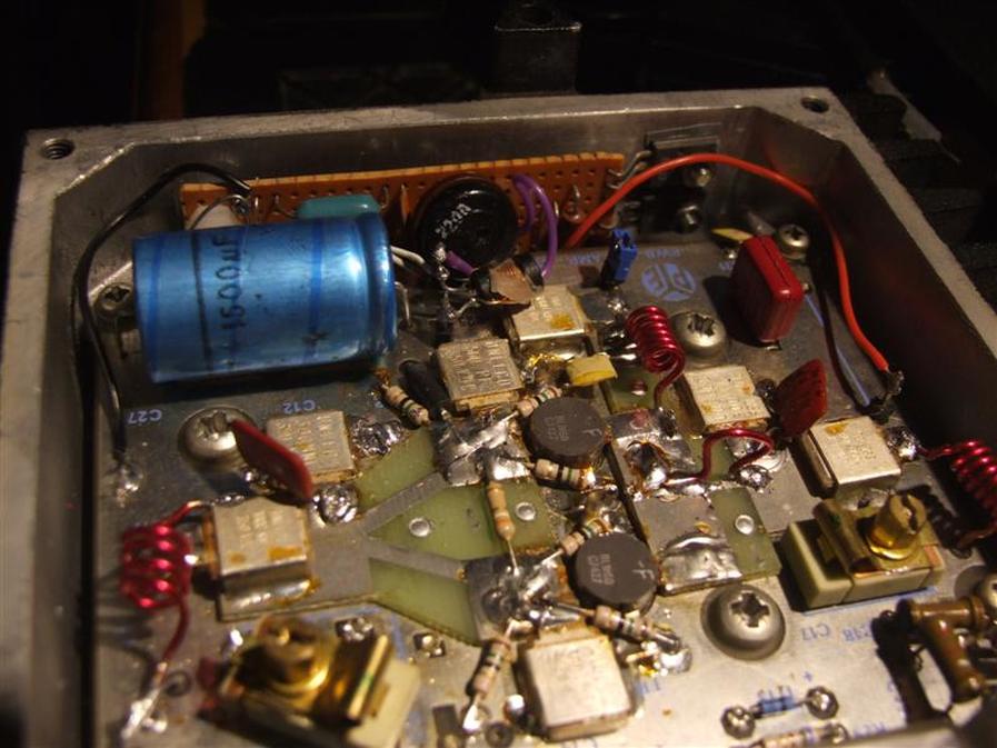
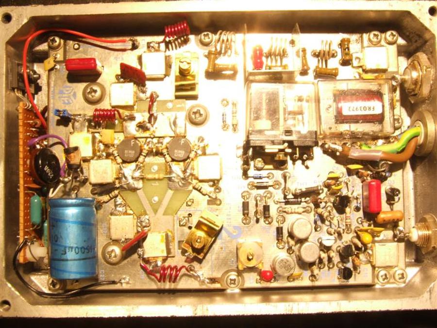
Mods to the pcb:
I couldn't get the input to match so reconfigured it.
remove R20 (between input tuning caps) and cut pcb track between where the inner end of R20 was and L2/C8 compression trimmer. Move the inner end of C8 to where R20 came out of, like 45 degrees.
also moved L2 to the other side of C11
I re-wound L2 and L8 to the number of turns shown on photos of E-band version, L8 and the little hairpin shown on the photo which is across the original track link which is L7 (with a cut in it !) The 'piggyback' pcb with stripline inductors allows for different frequency versions of the basic motherboard
I added silver mica caps where you see them on my photo (square red), value by experiment, think they were something like 120pf ?
Also made a new L9 on the +12v feed and made a blue pin link which gives a connection point for a current meter for setting the bias level.
you can see where I turned the compression trimmer sideways, you do need to take the pcb out to break the track underneath but it comes out ok, just remove the power cable connections and coax socket links.
I did not alter the output filter as I use a Pye 'black box' filter on the output which also removes the remnants of 42MHz oscillator leakage and any harmonics
I achieved approx 45w rf.from approx 5-6w ssb drive from a Trans4m Transverter (G3WIE kit off yahoo group) and G4DDK 7w driver pcb.
I hope these notes will help others who may be contemplating the conversion
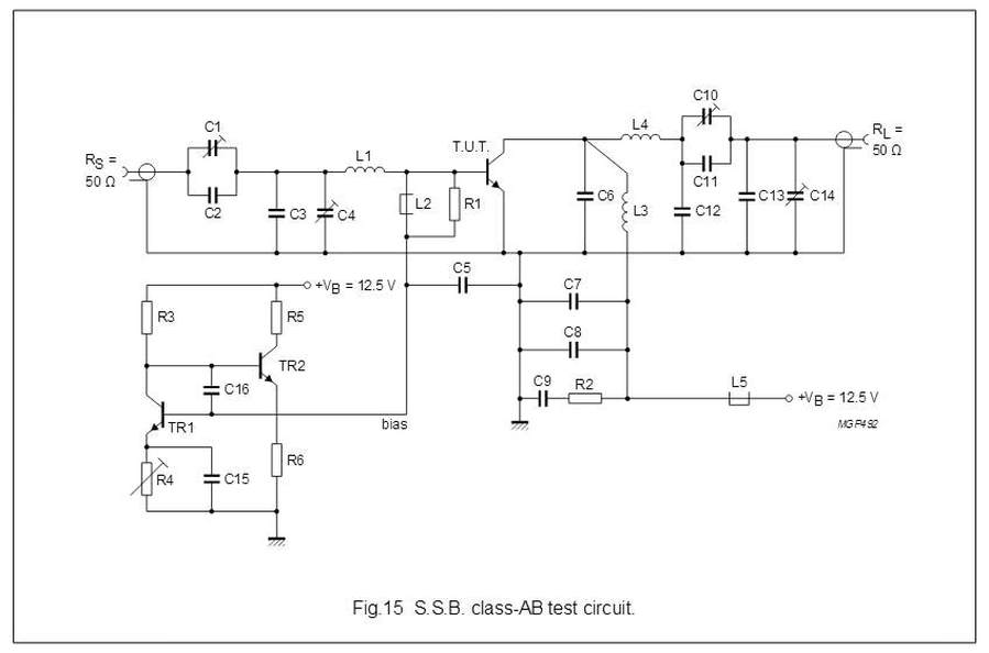
Here is the bias circuit from the data sheet